SimServer How To #1: Build and simulate OPC UA Data Models
22.03.2022
UPDATE 01.07.2022: The language used has been fact-checked and made clearer. The process chart at the beginning has been updated. Guide steps now include more explanations.
To get the most out of the Prosys OPC UA Simulation Server, it is essential to know how to build your simulated systems. In this article, you will learn how to create your information models, import them to the Simulation Server, and use them to your advantage by creating your Objects and Variables with custom Values. Finally, we will discuss how you can test and monitor your system with a client application.
But why should you care about simulating? There are a few situations for which simulation is essential. When you are assembling a new system or making changes to an old one, you want to make sure that everything works as it should. Sometimes the Real-life OPC UA Server is not available for testing because it has not been built yet, it is actively in use, or cannot be made available for other reasons. In these cases, using a virtual server can save you time and let you keep going with development.
Products
To follow this tutorial, you will need four products.
-
Prosys OPC UA Simulation Server
- The Free Edition of the software can be used for adding folders, Objects, and Variables.
- For importing and exporting information models, the Professional Edition is required. You can get an evaluation license for this purpose.
-
- This free client application is used for connecting to the Simulation Server and validating the new information model.
-
- The application is used for creating information models and exporting them in NodeSet format.
-
- These free NodeSets are used as a base, on top of which you can build your own information models.
The big picture
The following figure shows the process from having a physical system requiring a digital representation to getting that system up and running with a Real-life Server that uses OPC UA.
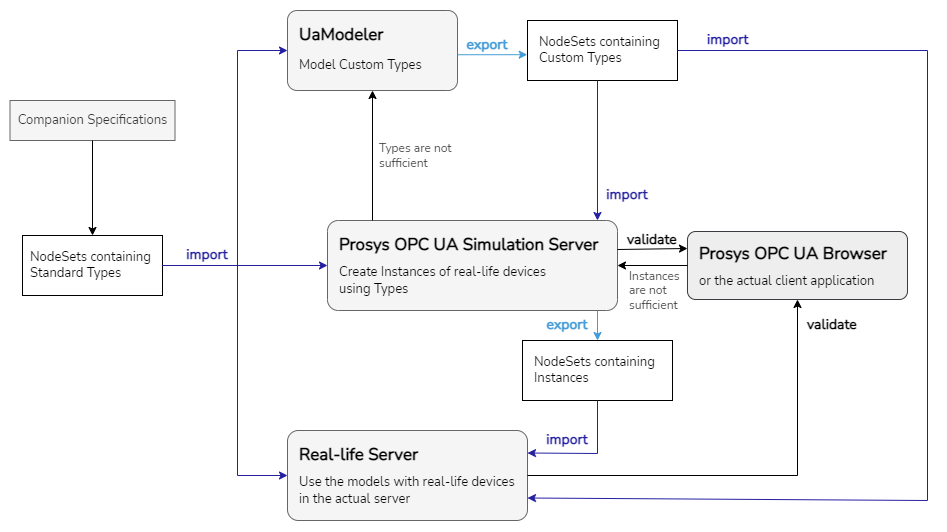
The most important thing you need for your system is an information model that represents the domain of your physical system. A model might already exist in the form of an OPC Foundation Companion Specification or another standard model. If this is not the case, you need to create your own model either on top of an existing one or a wholly new one. As you can see from the figure above, a sufficient information model can be imported as is to Simulation Server or your own Real-life Server, without having to go through UaModeler as well.
After modeling your Custom Types with UaModeler, the information model can be imported to Simulation Server. With Simulation Server, you can create Instances for your real-life devices with simulated Values to test your system. If the Types of the information model are sufficient, you can test and validate the simulated system using OPC UA Browser (or your own OPC UA Client application). If not, you need to go back to UaModeler to make changes to your model.
When everything seems to work correctly, you can export your Instances as a NodeSet file from the Simulation Server and import it into a Real-life OPC UA Server. The following sections will explain these steps more in-depth. To make this tutorial more fun, let’s say that we here at Prosys OPC have new devices that we want to be able to track and identify on an OPC UA server. Now we will go through the process of creating sufficient information models for our new devices.
We use different terms when we talk about information models in this article. According to the OPC UA specification, an information model is an “organizational framework that defines, characterizes and relates information resources of a given system”. When an information model is exported in XML format it follows the syntax defined by “Information Model XML Schema”. These files are referred to as NodeSet XML files. As you import NodeSets into the Simulation Server, you can see that Namespaces are created from those NodeSet files and added to the server’s NamespaceTable. Generally, each information model is created inside an unambiguously identified (NamespaceURI) Namespace to give them easily distinguishable names, so that is why you get a Namespace when importing an information model.
Finding and creating required information models (OPC UA Modeler)
When you have a new device or system that requires digital representation, Companion Specifications are a great place to start looking. These information models offer a variety of domains with ready-to-use Types for various cases. Every model uses the same standards, so compatibility between different models is seamless. If you don’t find quite what you need, you can easily build on top of these Companion Specifications with additions that suit your case the best. See our blog post on the Companion Specifications.
In our example case, we have gone through OPC Foundation’s Companion Specifications we downloaded here, and found that we could build on top of the DI model. We will add a Subtype for the DeviceType, and then add a string identifier for that Subtype.
How to create your NodeSet using DI information model
-
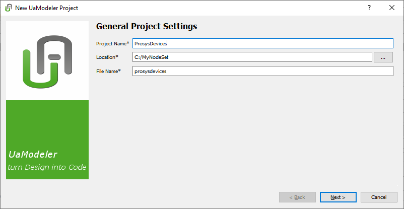
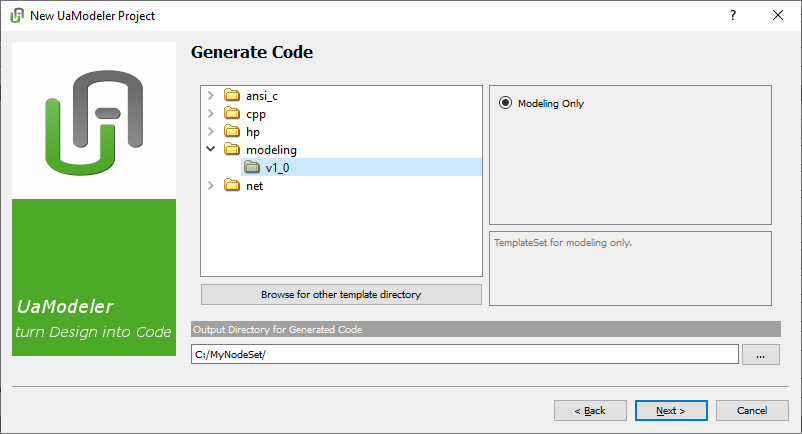
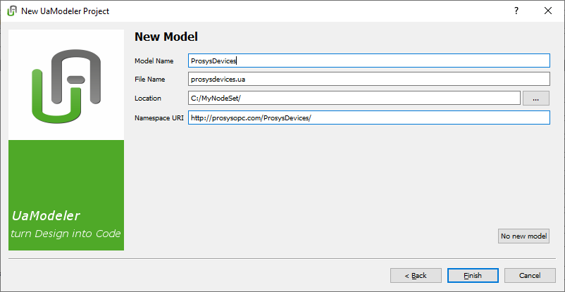
Create a new project.
-
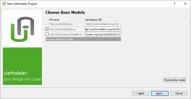
Choose the required models on top of which you are going to add. Opc.Ua.DI.NodeSet2.ua contains the model we want to use to create our new Type. That model is dependent on the model defined in Opc.Ua.NodeSet2.ua. We need to import both of those.
-
Define the information model’s name and Namespace URI. The URI will be visible on the server and will be used in identifying the model, so it should be descriptive.
-
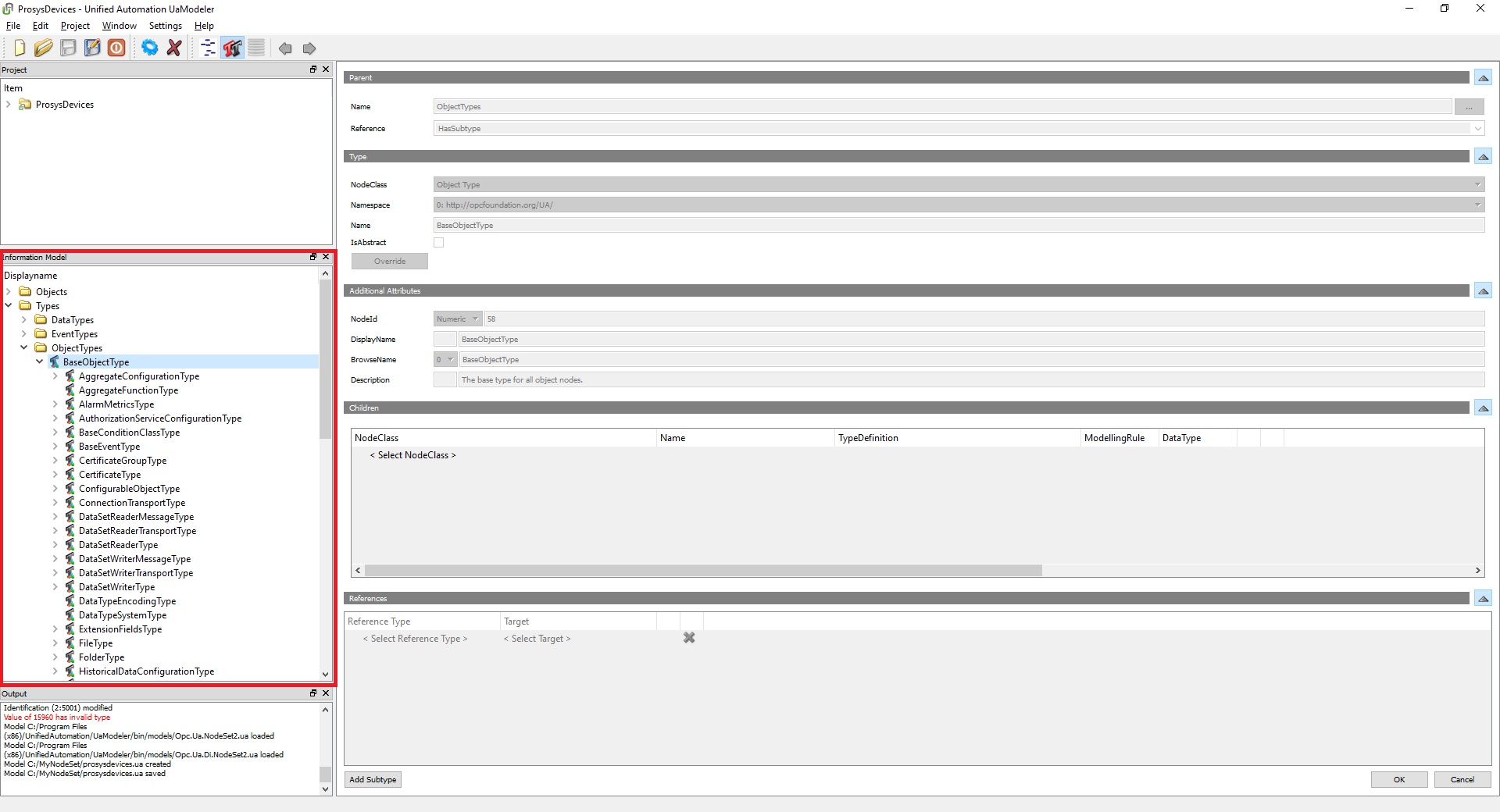
Browse the Information Model to find the Type you want to extend. The Information Model view lists everything from the linked information models you can use to define new Types. Those linked information models will be listed as dependencies for your information model, while any changes you make will appear in your model.
-
Go to Types > ObjectTypes >BaseObjectType > TopologyElementType > DeviceType. This is the Type for which we will add a new Subtype. The path can be found very easily by referencing the OPC Foundation’s documentation on the DI model. When you find the usable Type definition, you go backward to find the path.
-
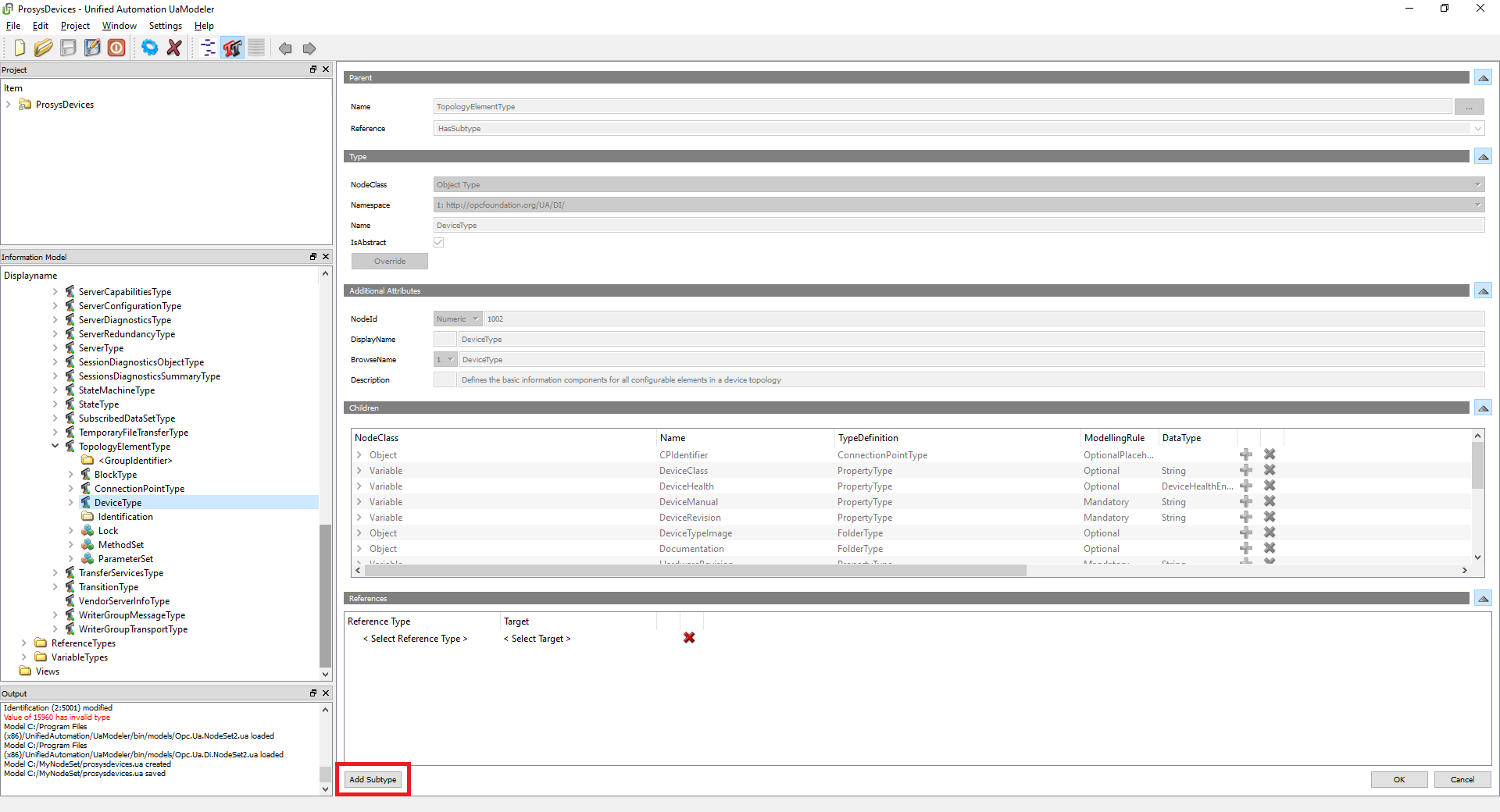
Click the Add Subtype button while DeviceType is selected. This will create a new Type that inherits all components and attributes from DeviceType.
-
Give a name for your Subtype. This Subtype will define the Type for our devices, so we name it “ProsysDeviceType”.
-
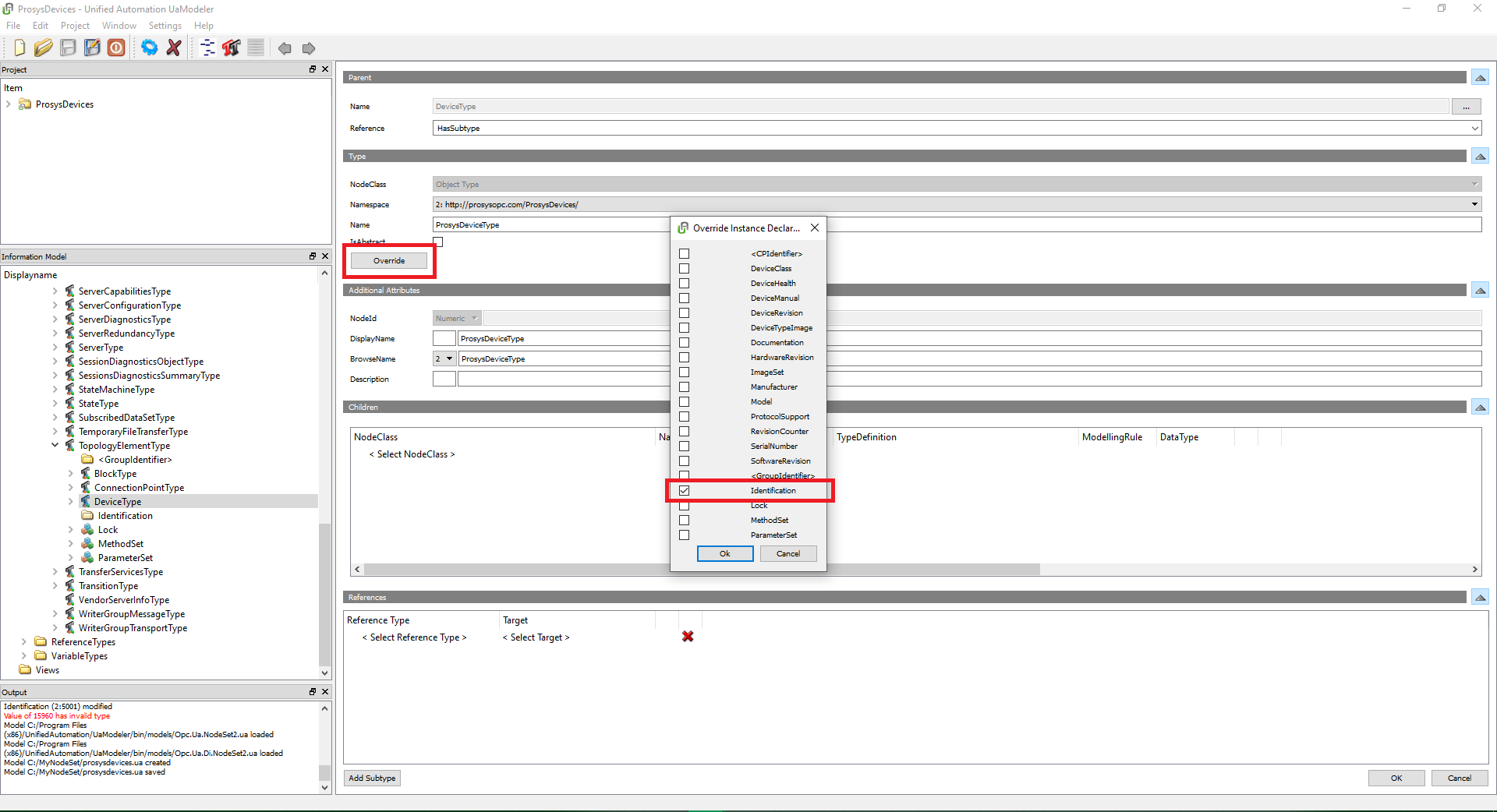
Click the Override button and select Identification on the dialog. This dialog lists all optional components that have been inherited for the Type. Click OK. Now the device Subtype has an Identification Folder.
-
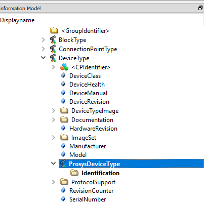
Click OK on the bottom right of the window. Now your Subtype has been added to the Information Model.
-
Next, we will add a Variable into the “Identification” Folder. Click on the “Identification” Folder in the Information Model.
-
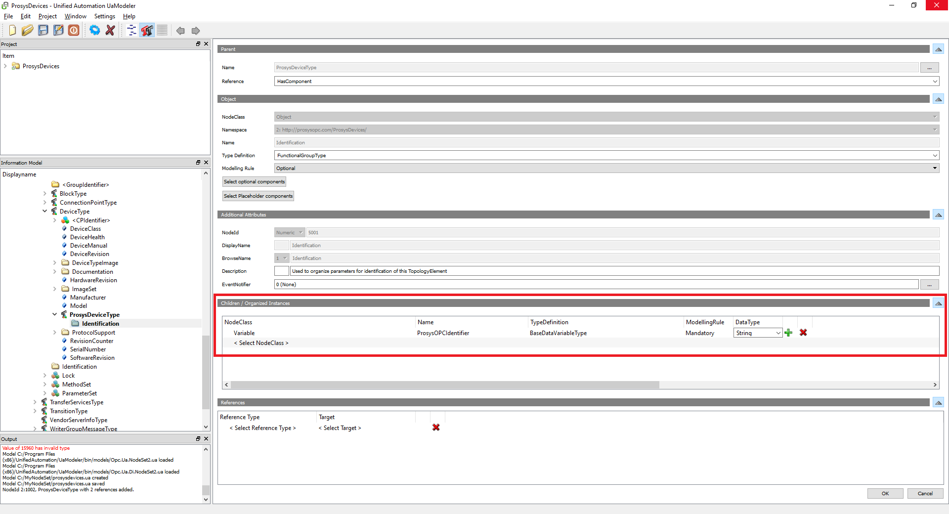
Add a new child for the Identification Folder.
Use these attributes:
- NodeClass: Variable
- Name: ProsysOPCIdentifier
- TypeDefinition: BaseDataVariableType
- ModellingRule: Mandatory
- DataType: String
-
Click OK again.
-
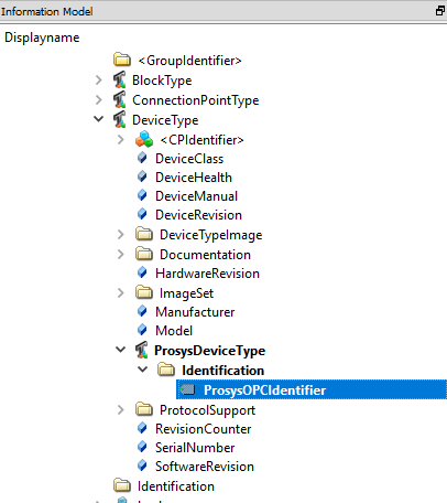
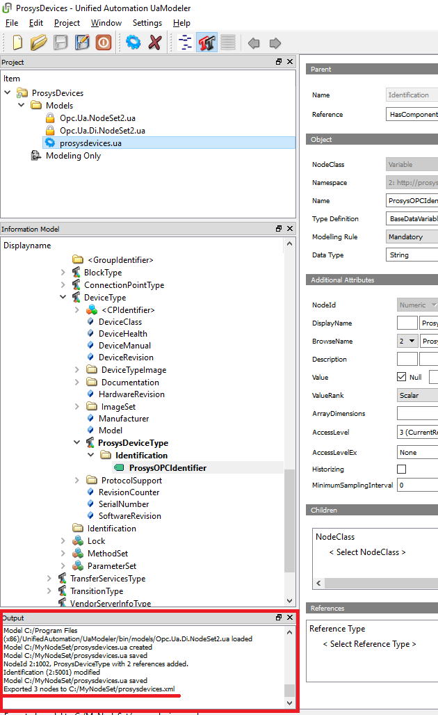
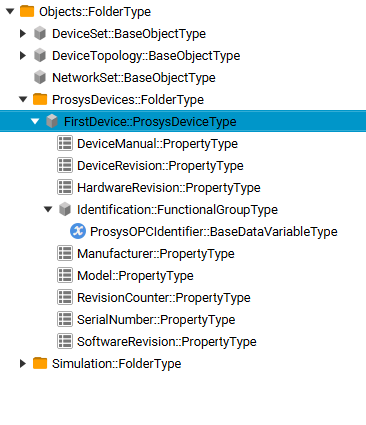
Check that your Information Model has a new Variable called “ProsysOPCIdentifier” inside “Identification”.
-
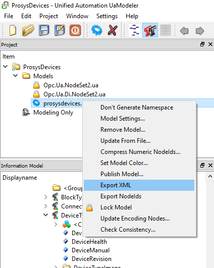
Go to the Project tree and find your model. Left-click and select Export XML.
-
Check the Output log for the saving location of your NodeSet.
If you would like to check out the files used in the tutorial, proceed by this link.
Importing information models into Prosys OPC UA Simulation Server
Now that we have a NodeSet that meets our requirements, we can import it into the Prosys OPC UA Simulation Server to create Instances of our new device Type. This is an important step because, with Instances, we can give the devices simulated Values that can then be observed to see how the information model works. This all can be done digitally, without a need to include the physical system or devices into the testing.
How to import your NodeSet into the Prosys OPC UA Simulation Server
-
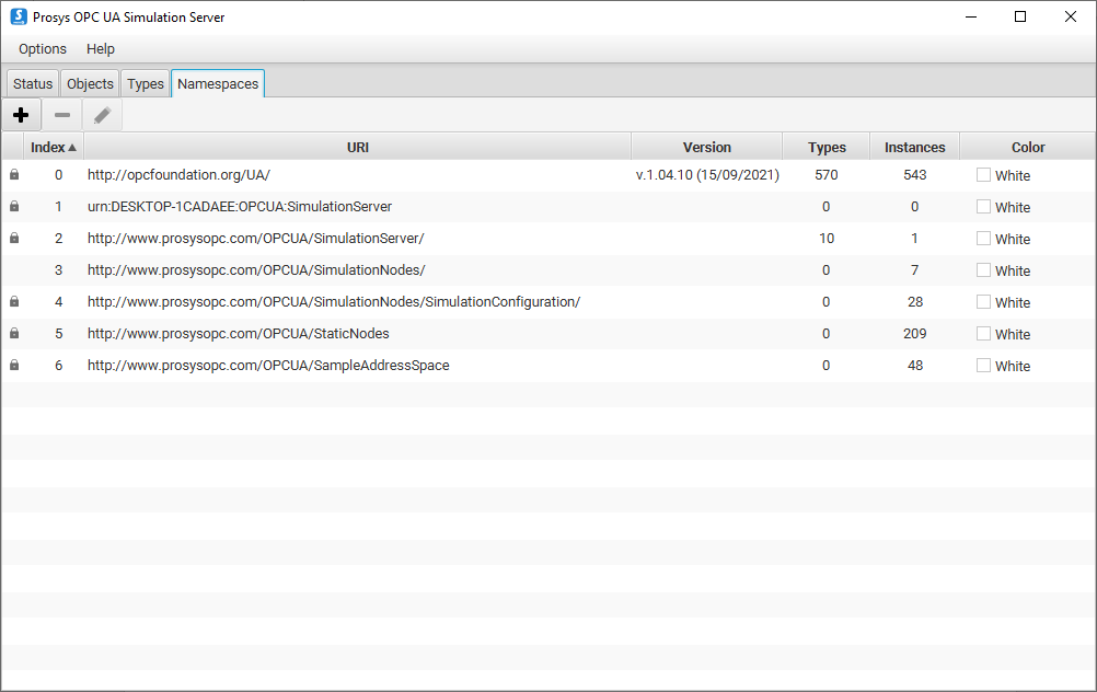
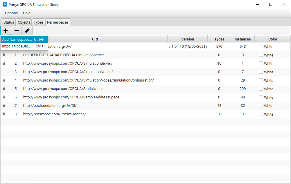
Run Prosys OPC UA Simulation Server and go to the Namespaces tab. Since Namespaces are what make information models’ names unique, it is best to list Namespaces instead of information models.
-
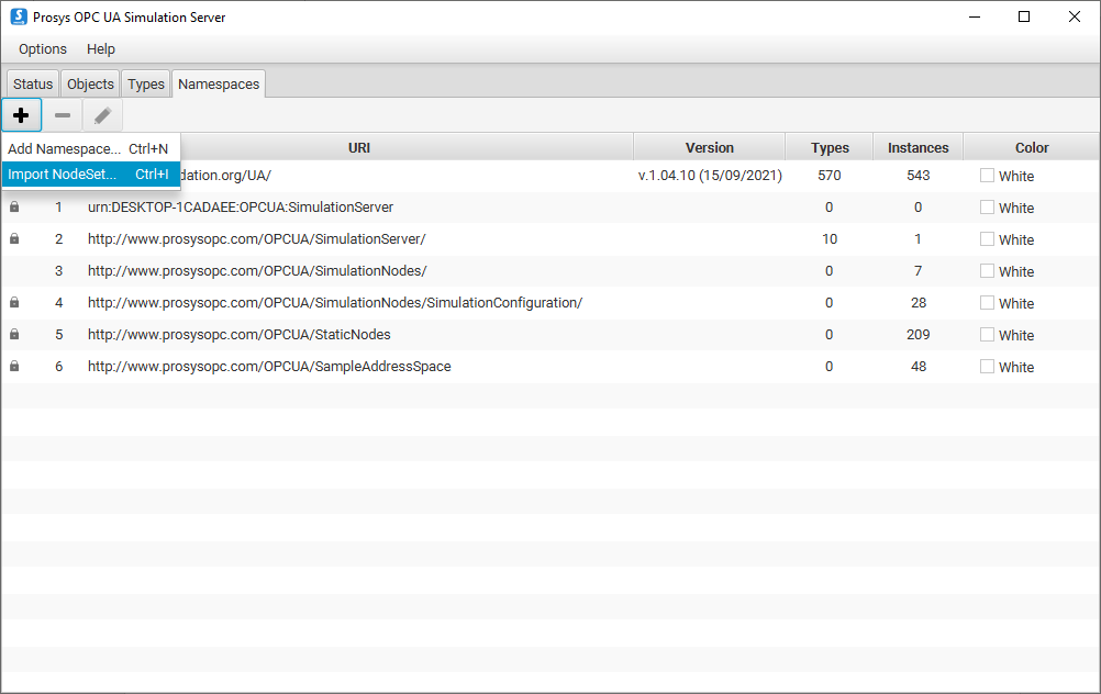
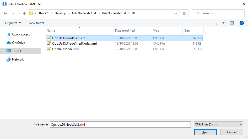
Since we used the DI information model to make our custom information model, the new model is dependent on the DI model, so we first must import that first. Click on the + button and select Import NodeSet.
-
Find and select the correct NodeSet file. Click OK to add the model to the Namespace table.
-
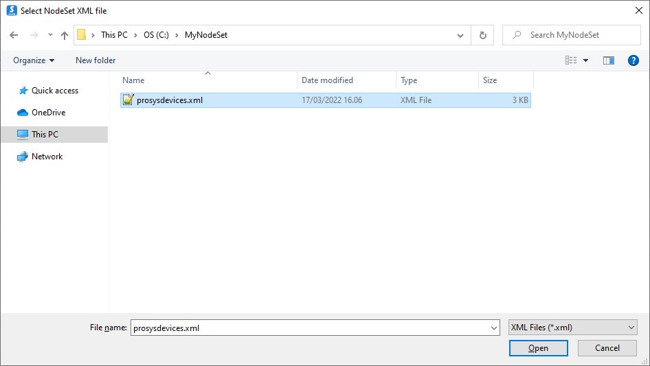
Click on the + and select Import NodeSet again. Now find and add the new NodeSet.
-
As you can see from the lock icons on the left, we cannot modify these Namespaces in any way. Let’s add one more Namespace for our Instances. Click on the + button again, but this time select Add Namespace. This will create an empty Namespace where we can add new Instances from the custom information model.
-
Give a URI for your new Namespace. Select a descriptive name. We will use http://www.prosysopc.com/OPCUA/ProsysDeviceInstances, which follows our naming practices.

Adding folders, Objects, and Variables to the simulated system
We have successfully imported our NodeSet into the Simulation Server. Next, we will create Instances and give the identifiers some initial values.
How to create Instances from your NodeSet on Prosys OPC UA Simulation Server
-
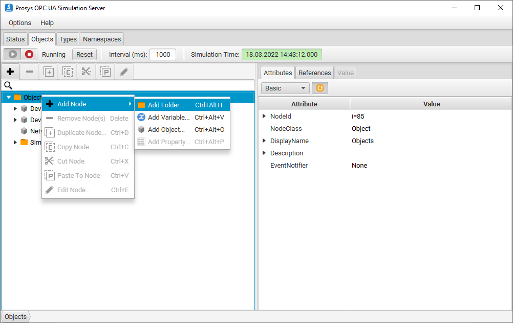
Go to the Objects tab to create Instances of our ProsysOPCDeviceType. Let’s add a new folder for our Instances first under Objects folder. The Objects folder contains all Objects on the server.
-
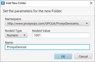
Select the newly added Namespace as the correct Namespace for the new folder. This way the folder and everything we add inside it are going to be added into that Namespace. Name your folder. We will use “ProsysDevices”.
-
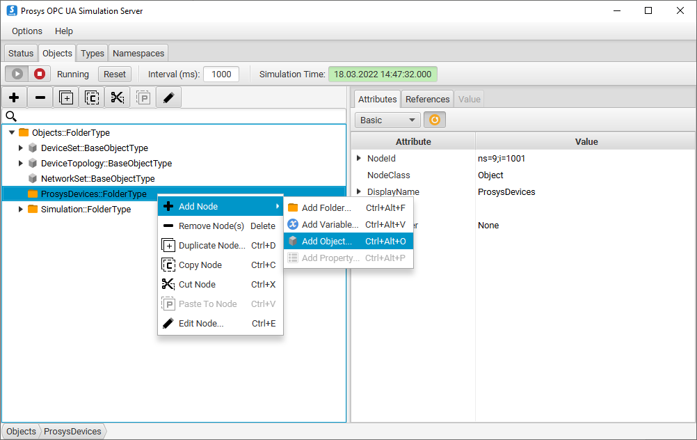
Now we will add some Objects into the folder. Right-click the folder and select Add Node > Add Object.
-
Make sure you have the correct Namespace selected and give the Object a name.
-
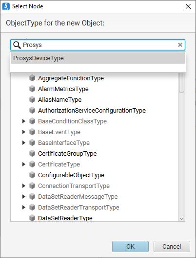
Click on the Type field to get a dialog where you can select the Type for the new Object. Next, find your own device Type. The easiest way to find your Type is to type the name of the Type into the search bar on top of the dialog. Select the correct Type and click OK. We have now created an Instance of that custom Type.
-
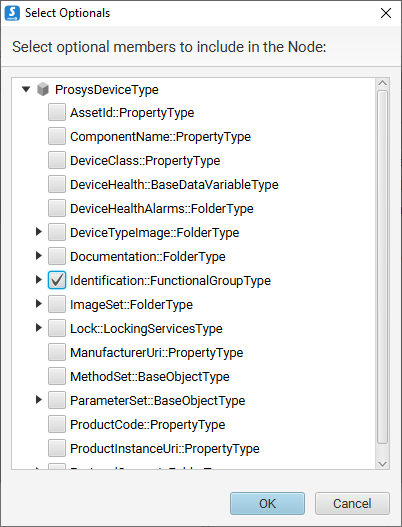
We want to add the identifier for the Object as well, so click on the Select Optional Members button to open a new dialog. This dialog shows every optional member the Type can have. Find the identifier and click OK.
-
Click OK on the Object creation dialog. Now you should have your first device listed inside the folder created in step 2.
-
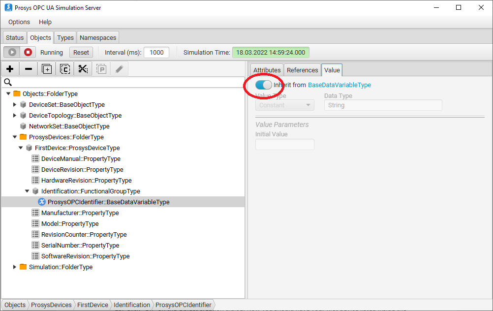
Now, we will give an Initial Value for the identifier. Select the identifier and open the Value tab. Disable Value inheritance from the switch on top of the Value tab. If you leave it enabled, you will not be able to set your custom value.
-
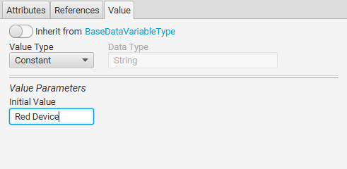
The Data Type of the identifier is String, so Value Type should remain constant. Write the identifier’s value to the Initial Value field.
-
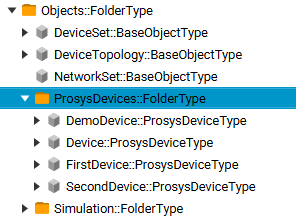
Follow steps 3-9 to create more Instances of your device Type.
-
When you are finished with your Instances, go back to the Namespaces tab. Right-click on the Namespace that was created for the Instances and select Export Namespace. This allows you to create a NodeSet of your new Namespace.
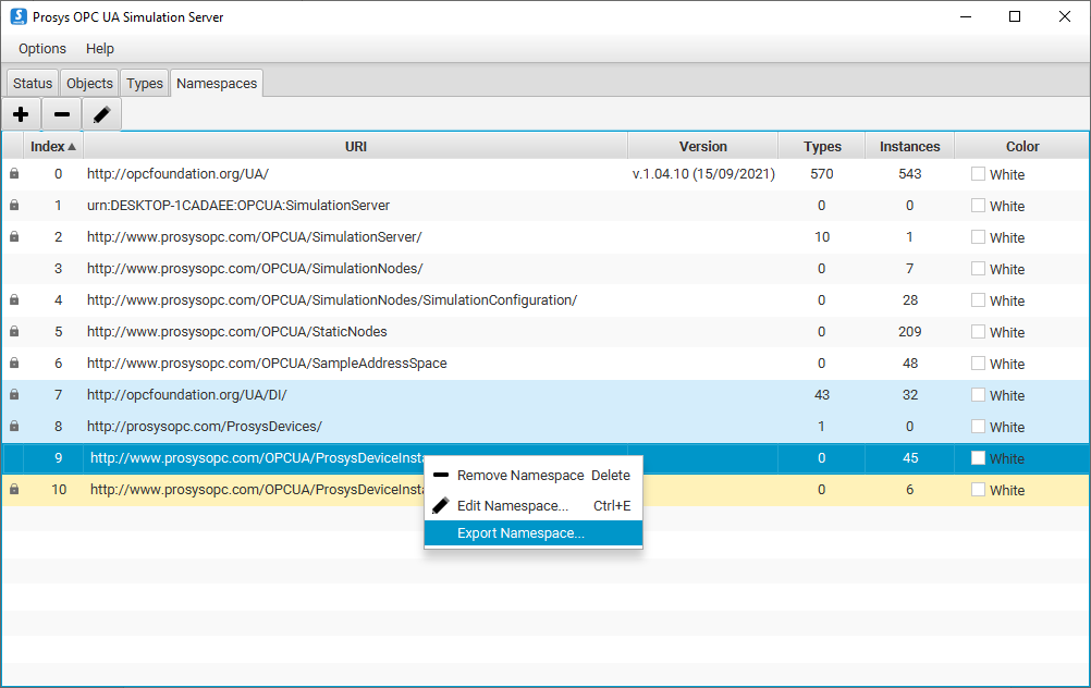
-
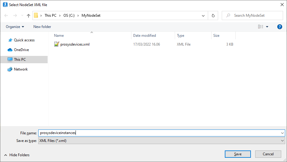
Select a location and file name for your new NodeSet. Then click Save.
-
Now you can find your new Instance NodeSet file from the folder you saved it to. Before importing it elsewhere, let’s test it using Prosys OPC UA Browser.
Monitoring and testing the simulated system
We have now arrived at the testing stage of our process. We will connect our Prosys OPC UA Browser to the Prosys OPC UA Simulation Server and find our new Instances from the Address Space. We can then read the values of the devices’ identifiers and make sure everything seems to work as we expected.
How to connect a client application to a server and find your Instances
-
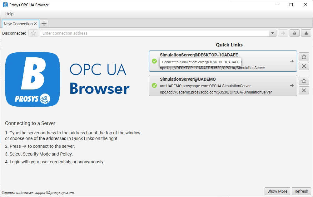
Run the Prosys OPC UA Browser and connect to the Simulation Server.
(You can copy the server’s connection address from the Status tab of the Prosys OPC UA Simulation Server).
-
Browse the Address Space on the left of the window. Go to Objects > ProsysDevices to find your devices.
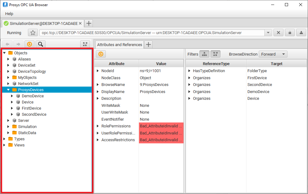
-
Go deeper into one of your devices: FirstDevice > Identification > ProsysOPCIdentifier. Select the Identifier to see its value on the Attributes and References tab.
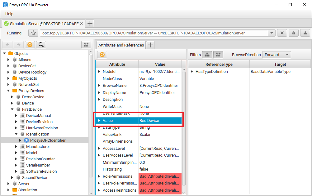
-
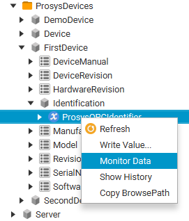
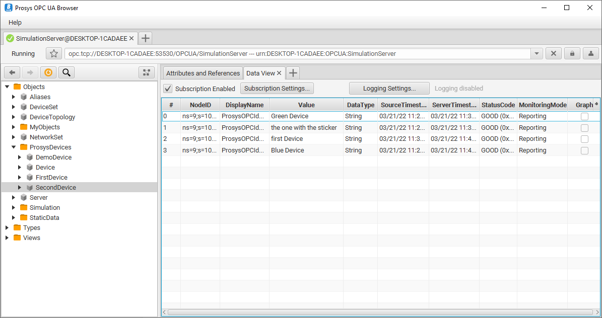
Right-click on the identifier and select Monitor Data to open a Data View tab where you can monitor your values.
-
Add the identifiers of all your devices to be monitored.
Next Steps
Keep in mind that this article presents a relatively simple case that is supposed to help you get started, and give you an idea how you can get the most out of the Prosys OPC UA Simulation Server. You can always come up with even more complicated systems and Types to create and test. If you have any questions while building your own systems and models, contact us at sales@prosysopc.com.
If you now want to do your implementation following this tutorial, place download requests for the following products:
- Prosys OPC UA Browser
- Prosys OPC UA Simulation Server
- You can use the Free Edition for adding folders, Objects, and Variables.
- For importing and exporting namespaces, you will need the Professional Edition.
- To receive evaluation or commercial license to unlock Professional Edition features, please contact sales@prosysopc.com.
- OPC UA Modeler
You might be wondering, what is next? Where to go from here with your newly exported Instance NodeSet? Stay tuned for our future posts to find out. You can subscribe to the RSS feed.

Kaisa Hirvola
Creative Engineer
Email:kaisa.hirvola@prosysopc.com
Tags: OPC UA, Information Models, NodeSet, Simulation Server, Guides
comments powered by DisqusAbout Prosys OPC Ltd
Prosys OPC is a leading provider of professional OPC software and services with over 20 years of experience in the field. OPC and OPC UA (Unified Architecture) are communications standards used especially by industrial and high-tech companies.
Newest blog posts
Why Do Standards Matter in Smart Manufacturing?
The blog post discusses the importance of standards in smart manufacturing, envisioning a future where auto-configurable systems in manufacturing rely on standardized data formats for seamless integration and reduced costs, with a focus on the OPC UA standard family as a key enabler.
OPC UA PubSub to Cloud via MQTT
Detailed overview of the demo presented at the OPC Foundation booth
SimServer How To #3: Simulate data changes on a server using an OPC UA client
A two-part step-by-step tutorial on how to write data changes on an OPC UA server using an OPC UA client.